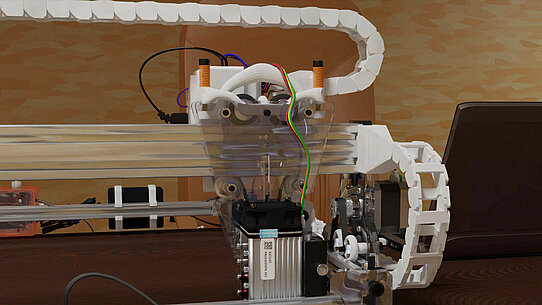
Laser Engraving Machine Upgrade
Firmware change
Actually I switched to GBRL because that's what I wanted from the start, when I bought it they said it was GRBL. But it was a system that was cobbled together from different ones and BenBox was used as the control software. This has its appeal, but I like Laser-GRBL much better.
Because opposite BenBox has Laser-GRBL
- a nicer user interface with more options
- runs more stable
- can be continued after interruption
- offers the possibility to execute processes several times
- is easier to configure because better documented
- etc. etc.
You hardly have to get used to it. The individual steps of the installation follow.
Load GRBL onto the controller
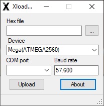
With Arduino 1.8.19 it was unsuccessful. To load the program onto the Arduino nano, I used Geir Lunde's XLoader. This was provided to me in 2012 when I was pestering the retailer why it's not real GRBL but was advertised as such.
- Download GRBL, https://github.com/Fehndruid/grbl/tree/laser-engraving-machine
- Adjust the config.h, 57600 baud rate for Nano (already included in the branch mentioned under 1.)
- Generate hex file (with Arduino), gbrl may need to be loaded into the Arduino Library
- Backing up the firmware with AVRDude (For me it looked something like this: avrdude -C avrdude.conf -c avrisp -P COM3 -b 57600 -p m328p -v -U flash:r:adduinoDownload.hex)
- Use XLoader to load the hex file onto the controller (possibly select ATmega328), which actually only uses AVRDude (see also https://adduino.com/upload-hex-file-on-arduino-using-avrdude-programming-avr-boards/)
- Then system variables had to be adjusted, see Setting up LaserGRBL
However, the laser stayed at less than 1% power no matter what settings I tried, for now.
Setup Laser GRBL
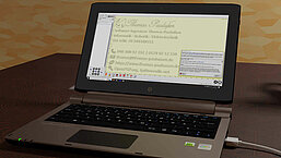
Which system variables had to be adjusted? This can be found in the settings.nc (see image on the left).
- Stepper motors, number of steps per mm
- No end stops
- laser port
- laser mode
- Spindle or PWM
Alternatively, $100 and $101 (travel resolution) can be calculated by measuring a distance driven. Quite simply with new_resolution = old_resolution * (entered_distance / driven_distance). Example: Resolution = 80 * ( 20 mm / 25 mm ) = 64 (If it drove further than intended, the resolution must decrease because it dictates the number of steps that are calculated to reach the distance).
Hardware changes
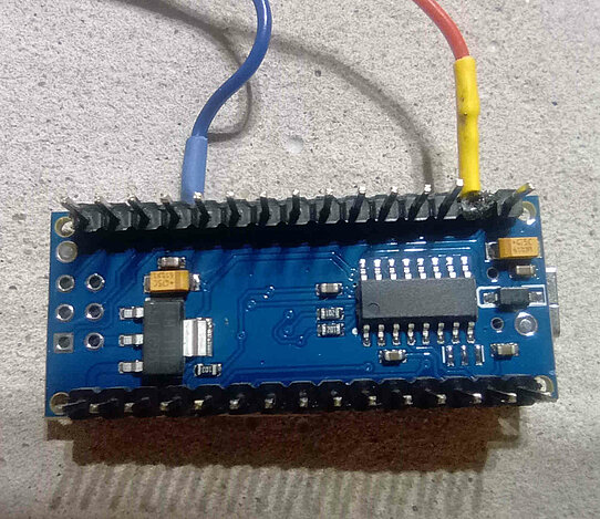
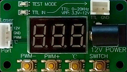
A few contacts have to be resoldered so that the TTL signal is correct and works with the new laser. The new laser control signal is sourced from Arduino Nano pin D11 and GND. (I wrote more about this on https://forum.neje99.com/t/ttl-pwm-issue-with-other-controller/3258 in English, a free account is required)
New hardware
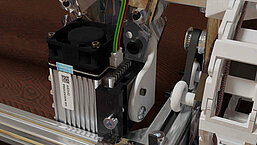
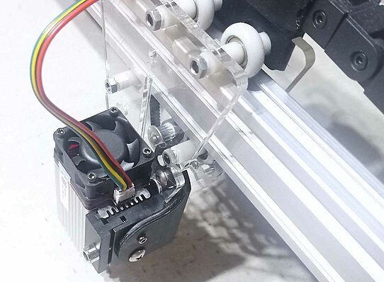
The new components are a laser driver, a power supply and a laser.
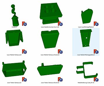
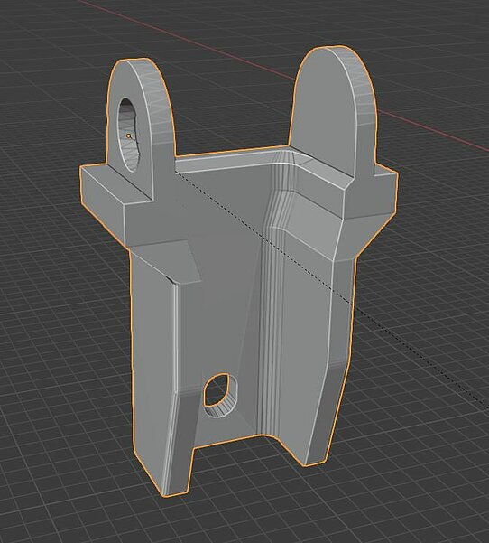
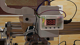
Because the power supply was welded to a plug for the outlet, I removed the case and printed a new one. This was provided with an attachment to the laser carriage so that the power supply cable, carrying 12 V voltage, is as short as possible and thus low-loss. The result is 101% power, but the manufacturer recommends working with less power to protect the laser and increase durability, and 20% is sufficient for many applications.
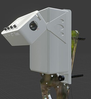
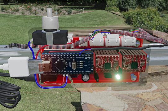
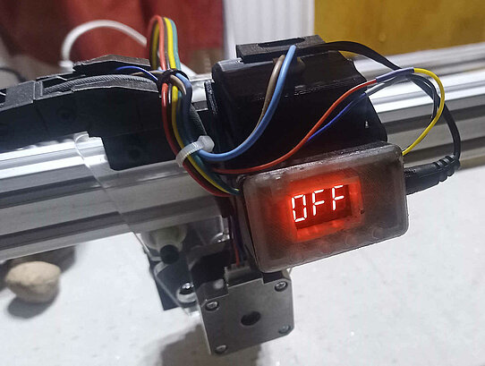
I placed the laser driver in a tiltable housing in front of the power supply unit, I chose the test module because I can use it to monitor the power and temperature.
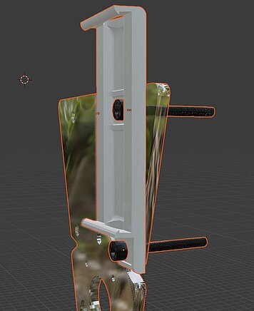
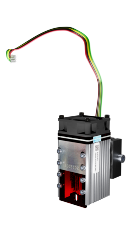
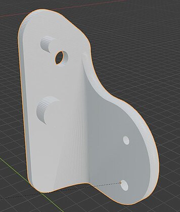
The laser has a height-adjustable adapter, which I mounted on the carriage with a printed angle.
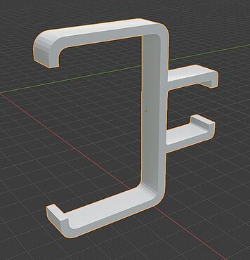
The original power supply was hooked to the aluminum profile using two clamps.
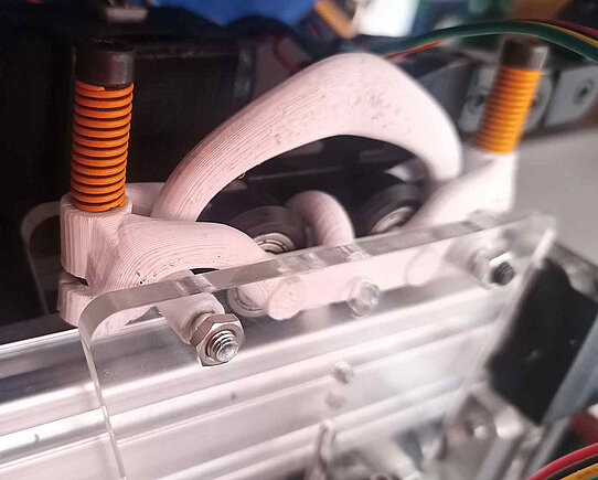
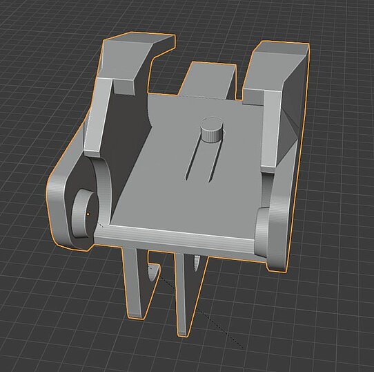
Last but not least, I developed a spring system for the upper wheels of the sled so that it is pressed firmly into the track, otherwise it tended to wobble.
Carriage spring system
The additional weight from the power pack and the heavier laser caused the carriage to sway on the X-axis. This is remedied with a little more pressure on the wheels and slightly stronger rollers.
Something could have been printed without springs that would apply sufficient tension, thanks to the elasticity of the print material. That same resiliency means the construction flexes a little too much, making the bolts easy to bind and the springs stiff.
The cable management system
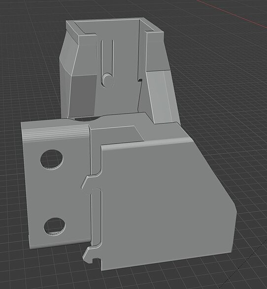
The small and somewhat flimsy links of the cable management system are sufficiently stable when they are mostly resting, as is the case here on the sides of the frame.
The end pieces were designed by me, the individual links only slightly adjusted by me. For the cable routing to the laser unit in the middle, the connecting pieces are compatible with a standard cable drag chain that I still had lying around.
Laser proof pad
What should my base be for the laser?
- Laserproof
- Fireproof
- Handy
Energy absorbing materials include dark aluminum and multilayer plastic panels. For my 10 watts, however, cement is completely sufficient, and it has more grip than a smooth aluminum plate. When I cut out labels, the cement keeps the sheets in place better. Moreover, unlike metal and plastic, cement cannot burn.
How do you make them?
- Saw the base to size, in my case an OSB panel (large particle board)
- Fastening some old boards or battens to the sides with screw clamps, I screwed them to the table I was working on. Of course, they have to close tightly, or maybe you should help with some modeling clay
- Because I decided to pour the slab just under a centimeter thick with cement, I got by with a good 5 liters and was also almost tight. It is advisable to lay out foil
Annotation
At the time I wrote the article, the work was almost a year ago and without documentation, but I hope that my explanation is reasonably complete.
Finally, the laser has a power that you can do something with. In the meantime, however, there are already some that use four diodes and thus achieve a laser power of 20W. However, a further increase only becomes interesting for me if you can use it to cut metals, but in my opinion one of these belongs in a sealed chamber with air extraction.
What did it bring?
- I have already engraved a few breakfast boards (this also worked before),
- pre-cut and punched leather for an armchair (this also worked before),
- cut out sealing rings (this took too much time before)
- cut out hundreds of stickers (this worked as well before)
- and cut wood (before that only worked with thin)
It was definitely worth it, because the old laser was already used up. And it's pleasing to see GRBL starting and stopping smoothly with variable acceleration, it seems really graceful, unlike before.
Download
The construction files can be found here on the following platforms.
- Cable management system, power supply housing, driver housing and mounting bracket, spring system, www.thingiverse.com/thing:5919457
Blender files
- Laptop, Laser engraving machine, Laser, www.turbosquid.com/Search/Artists/softwareing
Video
At first, the simulation was kept very simple in order to adapt parts. However, I found Blender so beautiful that I kept drawing. There was a lot to learn before turning this into a sim where you can change the text in one place and then when you re-bake and render it gets cropped out accordingly.
The lighting effects were only possible with Cycles, and it took a few tricks to get them right.
Sometimes it's late to find out what you thought was a bug in the program. For example, that in version 3.5 the script nodes for materials didn't run at all, in Cycles.
It would be interesting for me to know how you can do without increasing the frame rate if intermediate steps don't help because of the movement control via geometry nodes.
Comments
No Comments

